Planning Fiber Optics Networks (Electronics)
Contents:
Installers drill a hole through poles and install bolts that attach steel strands to the pole. Strands are then able to hang on the pole. Fiber optic cables are attached to the strand by being lashed on with wire. A cable lasher is used and pulled along the length of the fiber cable and strand. Splice cases and slack loops are added at various points along the network. A splice case is where each section of the fiber optic cable is joined together.
While the slack loop provides extra fiber cable to facilitate restoration of service in an event that the cable is damages. The splice case also provides a location where strands serving individual customers can be connected to the backbone fiber. A skilled technician heats the ends of the fiber strands and fuses them together to for a single strand. Once necessary deices are placed, engineers program and activate the service so it can be connected to. This can include basic data on the local geology, locations of road, buildings, underground and aerial utilities, and much more.
It is beyond the scope of this book to examine GISs in detail but the designer should learn how to utilize a GIS to create the design to facilitate not only the design of the cable plant but also create documentation for the network. It is important to understand the limitation of GIS. For example the type of ground along the route can determine the methods of underground installation, with deep soil permitting direct burial, other soils requiring trenching and conduit and rocky areas precluding underground installation of any type.
Aerial installations must be based on knowledge of the owners of the poles and the processes necessary to gain permission to use the poles and make ready for new cable installations. Do not use GIS alone. It is just one tool that can assist the designer but is not a replacement for traditional processes including site visits to evaluate the route. Governments and other organizations that control rights-of-way face a difficult problem in the Internet age - the continual digging up of their properties for cable plant installation.
It's not uncommon for roads to be dug up multiple times for different cable plant owners and operators. This is expensive and disruptive. A simple solution is what is generally referred to as "Dig Once," a process where the cable plant installer who digs up rights-of-way installs excess conduits or ducts for future cable plant installation. When installing one cable with its associated ducts or conduits, the installer adds in several extra ducts for future use on the route. The number and type of ducts is based on projected future uses but is probably a minimum of 2 to 5.
Future users lease duct space from the local authority and pull in their own cables. This "dig once" policy is especially useful in metropolitan areas where digging is most disruptive and cities looking at becoming "smart cities" find themselves in need of large fiber optic backbones to support desired services. Microtrenching is another method used for underground installation, generally on roadways or in private yards for fiber to the home connections. Microtrenching involves digging a narrow and shallow trench about 25mm 1 inch wide and mm inches deep using a special tool.
Tools are available that can cut through asphalt or concrete roadways or sidewalks or for cutting in bare ground. After cutting the trench, one can install a special cable or microducts in which cables can be installed by blowing. A typical trench can accommodate a microduct with up to six ducts providing for future expansion.
Planning For A Safe Installation. Safety is an important part of the planning process for any fiber optic installation. Later in this chapter, we have a section called " Safety In Working With Optical Fiber" that covers the issues specific to dealing with optical fiber when preparing cables and splicing, terminating and testing them. But with any installation there are many other aspects of safety that the installer must consider. Work areas for OSP installation are often near roads, railways, utilities or other areas with potential hazards.
Digging trenches or directional boring requires knowing where underground utilities are located and confirming their locations before final digging.
Tools & Media
Premises installations often require working near power cables and other indoor utilities, as well as workers who may be in a building during the installation. The installer is expected to know and follow all laws, codes and local requirements for safe installations such as those by agencies like OSHA in the USA. Workers should be trained in these practices also. Work sites should have safety regulations posted including required safety gear to be worn by workers and supervisors should monitor the site to ensure these rules are followed.
Fiber Optic Network Design.
Network Planning and Engineering for Fiber Optic Transport Systems
It includes first determining the type of communication system s which will be carried over the network, the geographic layout premises, campus, outside plant OSP, etc. Designing a fiber optic network usually also requires interfacing to other networks which may be connected over copper cabling and wireless.
Next to consider are requirements for permits, easements, permissions and inspections. Once we get to that stage, we can consider actual component selection, placement, installation practices, testing, troubleshooting and network equipment installation and startup. Finally, we have to consider documentation, maintenance and planning for restoration in event of a future outage.
The design of the network must precede not only the installation itself, but it must be completed to estimate the cost of the project and, for the contractor, bid on the job. Design not only affects the technical aspects of the installation, but the business aspects also. Finally, a fiber optic network designer needs to understand the processes of installation. We recommend you review the FOA Guide sections on fiber optic installation covering basic fiber installation and OSP fiber installation.
Campus network design Working With Others Designing a network requires working with other personnel involved in the project, even beyond the customer. These may include network engineers usually from IT information technology departments, architects and engineers overseeing a major project and contractors involved with building the projects. Even company non-technical management may become involved when parts of the system are desired to be on exhibit to visitors.
Designers should have an in-depth knowledge of fiber optic components and systems and installation processes as well as all applicable standards, codes and any other local regulations. They must also be familiar with most telecom technology cabled or wireless , site surveys, local politics, codes and standards, and where to find experts in those fields when help is needed. Obviously, the fiber optic network designer must be familiar with electrical power systems, since the electronic hardware must be provided with high quality uninterruptible power at every location. And if they work for a contractor, estimating will be a very important issue, as that is where a profit or loss can be determined!
Experience with CAD systems is a definite plus. The Communications System Before one can begin to design a fiber optic cable plant, one needs to establish with the end user or network owner where the network will be built and what communications signals it will carry. The contractor should be familiar with premises networks, where computer networks LANs or local area networks and security systems use structured cabling systems built around well-defined industry standards. Once the cabling exits a building, even for short links for example in a campus or metropolitan network, requirements for fiber and cable types change.
Long distance links for telecommunications, CATV or utility networks have other, more stringent requirements, necessary to support longer high speed links, that must be considered. But while the contractor generally considers the cabling requirements first, the real design starts with the communications system requirements established by the end user.
- Mr. Smythe.
- The Unauthorized Guide to Doing Business the Richard Branson Way: 10 Secrets of the Worlds Greatest ?
- Luring Lucy: A Novella?
- .
- Planning Fiber Optics Networks.
- .
- Murder In a Lane.
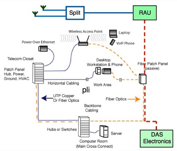
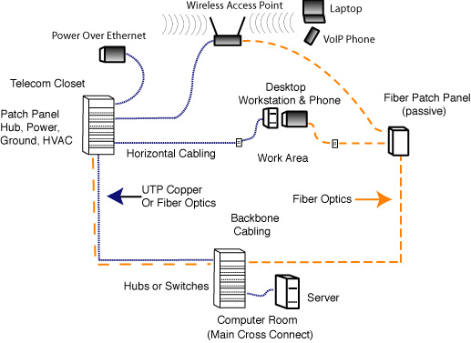
The communications equipment will determine if fiber is necessary or preferable and what type of fiber is required. Premises Networks Premises cable systems are designed to carry computer networks LANs, local area networks based on Ethernet which currently may operate at speeds from 10 megabits per second to 10 gigabits per second. The typical LAN has copper and fiber sections and links to connect to wireless access points for universal WiFi connectivity. Data centers are unique applications that house multiple Internet servers and storage networks operating at very high speeds using combinations of short copper and fiber links.
Other systems may carry security systems with digital or analog video, perimeter alarms or entry systems, which are usually low speeds, at least as far as fiber is concerned.
This book shows you how to effectively design and deploy bandwidth-rich networks for all major types of data traffic. Planning Fiber Optic Networks describes. Planning Fiber Optic Networks can benefit the following profession- als: engineers as a plane transverse electromagnetic (TEM) wave with the electric.
Premises telephone systems can be carried on traditional twisted pair cables or, as is becoming more common, utilize LAN cabling with voice over IP VoIP technology. Premises networks are usually short, often less than the meters about feet used as the limit for standardized structured cabling systems that allow twisted pair copper or fiber optic cabling, with backbones on campus networks used in industrial complexes or institutions as long as m or more, requiring optical fiber.
Between multiplexing and demultiplexing points in a DWDM system, there is an area in which multiple wavelengths exist The OSC carries information about the multi-wavelength optical signal as well as remote conditions at the optical terminal. Some of these links have been available for decades, as industrial applications were some of the first premises uses of fiber optics, dating back to before A link loss budget encompasses items such as the length of the link, fiber type, wavelengths, connectors and splices, and any other sources of loss in the link. Some obstacles may be found during site visits, where signs like these are visible. Sign in Username Password Forgot password? Media converters will also allow the choice of media appropriate for the customer application, allowing use with multimode or singlemode fiber and may even offer transceiver options for the distance that must be covered by the link. The outer jacket is moisture-resistant for outdoor use but can be easily stripped, leaving the fire-rated inner jacket for indoor runs.
Premises networks generally operate over multimode fiber. Premises networks will include a entrance facility where outside plant and premises communications systems meet. This facility must include not only cabling connections but compatible communications equipment. Since it is indoors, it must consider issues for building and electrical codes, such as the common requirement that bare OSP cables can only come 50 feet about 15 meters before being terminated in fire-rated cables unless it is in conduit.
Outside Plant Networks Outside plant networks refers to all systems that are outdoors, not inside buildings or campuses.
They are typically longer networks uses for telecom, CATV, utilities, security, metropolitan networks, etc. Telephone networks are mainly outside plant OSP systems, connecting buildings over distances as short as a few hundred meters to hundreds or thousands of kilometers. Data rates for telecom are typically 2.
The big push for telecom is now taking fiber directly to a commercial building or the home, since the signals are now too fast for traditional twisted copper pairs. CATV also uses singlemode fibers with systems that are either hybrid fiber-coax HFC or digital where the backbone is fiber and the connection to the home is on coax. Coax still works for CATV since it has very high bandwidth itself. Some CATV providers have discussed or even tried some fiber to the home, but have not seen the economics become attractive yet.
Security monitoring systems in large buildings like airports, government and commercial buildings, casinos, etc. Like other networks, premises applications are usually multimode while OSP is singlemode to support longer links. Metropolitan networks owned and operated by cities can carry a variety of traffic, including surveillance cameras, emergency services, educational systems, telephone, LAN, security, traffic monitoring and control and sometimes even traffic for commercial interests using leased bandwidth on dark fibers or city-owned fibers.
However, since most are designed to support longer links than premises or campus applications, singlemode is the fiber of choice.
For all except premises applications, fiber is the communications medium of choice, since its greater distance and bandwidth capabilities make it either the only choice or considerably less expensive than copper or wireless. Only inside buildings is there a choice to be made, and that choice is affected by economics, network architecture and the tradition of using copper inside buildings. Cabling Design Copper, Fiber or Wireless? Communications technology and the end user market, it seems, have already made decisions that generally dictate the media and many networks combine all three.
The designer of cabling networks, especially fiber optic networks, and their customers today generally have a pretty easy task deciding which media to use once the communications systems are chosen. Long Distance and Outside Plant Cabling Other than telco systems that still use copper for the final connection to the home, practically every cable in the telephone system is fiber optic.
CATV companies use a high performance coax into the home, but it connects to a fiber optic backbone. The Internet backbone is all fiber. Most commercial buildings in populous areas have direct fiber connections from communications suppliers. Cities use SM fiber to connect municipal buildings, surveillance cameras, traffic signals and sometimes offer commercial and residential connections, all over singlemode fiber. Even cellular antenna towers along highways and on tall buildings usually have fiber connections. Remote areas such as central Africa depend on satellite communications since cables are too expensive to run long distances for the small amounts of traffic involved.
Designing long distance or outside plant applications generally means choosing cabling containing singlemode SM fiber over all other media. Most of these systems are designed to be used over distances and speeds that preclude anything but SM fiber. Occasionally other options may be more cost effective, for example if a company has two buildings on opposite sides of a highway, a line-of-sight or radio optical wireless network may be easier to use since they have lower cost of installation and are easier to obtain relevant permits. The choice of the actual singlemode fiber, however, can depend on the application.
Depending on the length of the link, the wavelength of the transmitters, data rate of the transmission and if CWDM or DWDM are planned, different types of fiber may be optimal. Refer to the section on on fiber for more details. Premises Cabling The desire for mobility, along with the expansion of connected services, appears to lead to a new type of corporate network.
Surveillance systems are becoming more prevalent in buildings, especially governmental, banking, or other buildings that are considered possible security risks. While coax connections are common in short links and structured cabling advocates say you can run cameras limited distances on Cat 5E or Cat 6 UPT like computer networks, fiber has become a much more common choice. Besides offering greater flexibility in camera placement because of its distance capability, fiber optic cabling is much smaller and lightweight, allowing easier installation, especially in older facilities like airports or large buildings that may have available spaces already filled with many generations of copper cabling.
When these premises communications systems connect to the outside world, it is generally to singlemode optical fiber. The entrance facility and equipment room must accommodate the equipment needed to make those connections. Use of Cabling Standards Many documents relating to cable plant design focus on industry standards for both communications systems and cable plants.
It is important to realize why and by whom these standards are written. Choosing Transmission Equipment And Links Choosing transmission equipment is the next step in designing a fiber optic network. This step will usually be a cooperative venture involving the customer, who knows what kinds of data they need to communicate, the designer and installer, and the manufacturers of transmission equipment. Transmission equipment and the cable plant are tightly interrelated. The distance and bandwidth will help determine the fiber type necessary and that will dictate the optical interfaces on the cable plant.
The ease of choosing equipment may depend on the type of communications equipment needed. Telecom has been standardized on fiber optics for 30 years now, so they have plenty of experience building and installing equipment. Since most telecom equipment uses industry conventions, you can usually find equipment for telecom transmission that will be available for short links usually metropolitan networks, maybe up to km , long distance and then really long distance like undersea runs.
All run on singlemode fiber, but may specify different types of singlemode. Shorter telecom links will use nm lasers on regular singlemode fiber, often referred to as G. Longer links will use a dispersion-shifted fiber optimized for operation with nm lasers G. For most applications, one of these will be used. Most telco equipment companies offer both options. Most CATV links are AM analog systems based on special highly linear lasers called distributed feedback DFB lasers using either nm or nm operating on regular singlemode fibers.
As CATV moves to digital transmission, it will use technology more like telecom, which is already all digital. The choices become more complex when it comes to data and CCTV because the applications are so varied and standards may not exist.
Table of Contents
In addition, equipment may not be available with fiber optic transmission options, requiring conversion from copper ports to fiber using devices called media converters. You can read the standards and see how far each equipment option can transmit over different types of fiber, choosing the one that meets your needs. Most network hardware like switches or routers are available with optional fiber optic interfaces, but PCs generally only come with UTP copper interfaces that require media converters.
Media converters will also allow the choice of media appropriate for the customer application, allowing use with multimode or singlemode fiber and may even offer transceiver options for the distance that must be covered by the link. CCTV is a similar application. More cameras now come with fiber interfaces since so many CCTV systems are in locations like big buildings, airports, or areas where the distances exceed the capability of coax transmission.
If not, video media converters, usually available from the same vendors as the Ethernet media converters, are readily available and also inexpensive. Again, choose converters that meet the link requirements set by the customer application, which in the case of video, not only includes distance but also functions, as some video links carry control signals to the camera for camera pan, zoom and tilt in addition to video back to a central location.
What about industrial data links? Many factories use fiber optics for its immunity to electromagnetic interference. But industrial links may use proprietary means to send data converted from old copper standards like RS, the ancient serial interface once available on every PC, SCADA popular in the utility industry, or even simple relay closures. Many companies that build these control links offer fiber optic interfaces themselves in response to customer requests.
Some of these links have been available for decades, as industrial applications were some of the first premises uses of fiber optics, dating back to before Most operate over regular graded-index multimode fiber although some have been designed around large core PCS plastic-clad silica fibers. While the telecom and CATV applications are cut and dried and the data Ethernet applications covered by standards, it is our experience that not all manufacturers specify their products in exactly the same way.
One company in the industrial marketplace offered about fifteen different fiber optic products, mainly media converters for their control equipment. However, those fifteen products had been designed by at least a dozen different engineers, not all of whom were familiar with fiber optics and especially fiber jargon and specifications.
As a result, one could not compare the products to make a choice or design them into a network based on specifications.
Until their design, sales and applications engineers were trained in fiber optics and created guidelines for product applications, they suffered from continual problems in customer application. The only way to make sure you are choosing the proper transmission equipment is to make absolutely certain the customer and equipment vendor — and you — are communicating clearly what you are planning to do.
One thing to remember — every installation will be unique. The actual placement of the cable plant will be determined by the physical locations along the route, local building codes or laws and other individuals involved in the designs. As usual, premises and outside plant installations are different so we will consider them separately.
Premises and campus installations can be simpler since the physical area involved is smaller and the options fewer. Having access to them means you have someone to ask for information and advice. Hopefully the drawings are available as CAD files so you can have a copy to do the network cabling design in your computer, which makes tweaking and documenting the design so much easier. If the building is still in the design stage, you may have the opportunity to provide inputs on the needs of the cable plant. Ideally, that means you can influence the location of equipment rooms, routing of cable trays and conduits, availability of adequate conditioned power and separate data grounds, sufficient air-conditioning and other needs of the network.
Outside plant OSP cabling installations have enormous variety depending on the route the cable must take. The route may cross long lengths of open fields, run along paved rural or urban roads, cross roads, ravines, rivers or lakes, or, more likely, some combination of all of these.
It could require buried cables, aerial cables or underwater cables. Cable may be in conduit, innerduct or direct buried, aerial cables may be self-supporting or lashed to a messenger. Longer runs often include crossing water, so the cable may be underwater or be lashed across a bridge with other cables. GIS Geographic Information Systems Outside plant installations depend heavily on maps and data about the cable plant route.
Site Visits And as soon as possible, you must visit the site or route where the network will be installed. Outside plant routes need to be driven or walked every foot of the way to determine the best options for cable placement, obstacles to be avoided or overcome, and to determine what local entities may have input into the routing. Often cities or other governments will know of available conduits or rules on using utility poles that can save design time and effort. For installations inside current buildings, you should inspect every area to be absolutely certain you know what the building really looks like and then mark up drawings to reflect reality, especially all obstacles to running cabling and hardware and walls requiring firestopping that are not on the current drawings.
Take pictures if you can. For buildings under construction, a site visit is still a good idea, just to get a feeling of what the final structure will be like and to get to know the construction managers you will be working with. They may be the best source of information on who the local authorities are who will be inspecting your work and what they expect. With a good map. Creating a route map is the first step, noting other utilities along the route on that map, and checking with groups that document the current utilities to prevent contractors from damaging currently installed pipes and cables.
- Winning at Leadership: How to Become an Effective Leader
- Calcium in Human Health (Nutrition and Health)
- Down South: One Tour in Vietnam
- Retrotransposition, Diversity and the Brain (Research and Perspectives in Neurosciences)
- The Wombles
- Corso di Informatica (Italian Edition)
- The Herschel Objects and How to Observe Them: Exploring Sir William Herschels Star Clusters, Nebulae